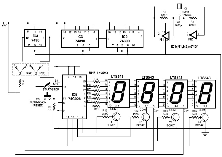
0 59 Counter Circuit Diagram
0 59 Counter Circuit Diagram. However, in many cases the resistance necessary to activate the beeper when you This circuit lets you adjust the threshold between bad and good contacts to suit your needs. If a counter resets itself after counting n bits is called "Mod- n.
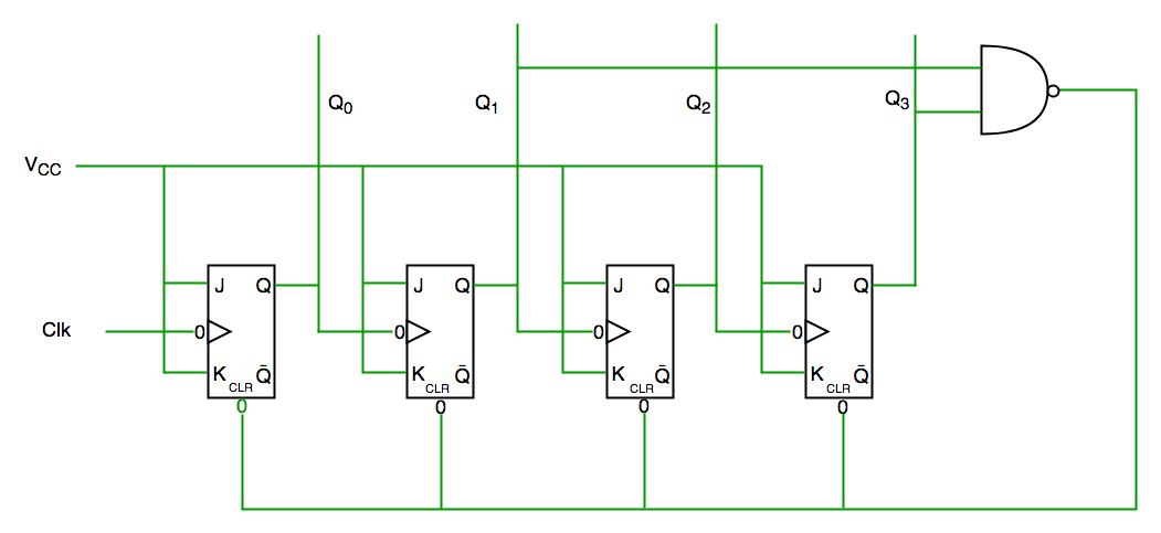
The state diagram of Decade counter is given below.
Polish your personal project or design with these Circuit Diagram transparent PNG images, make it even more personalized and more attractive.
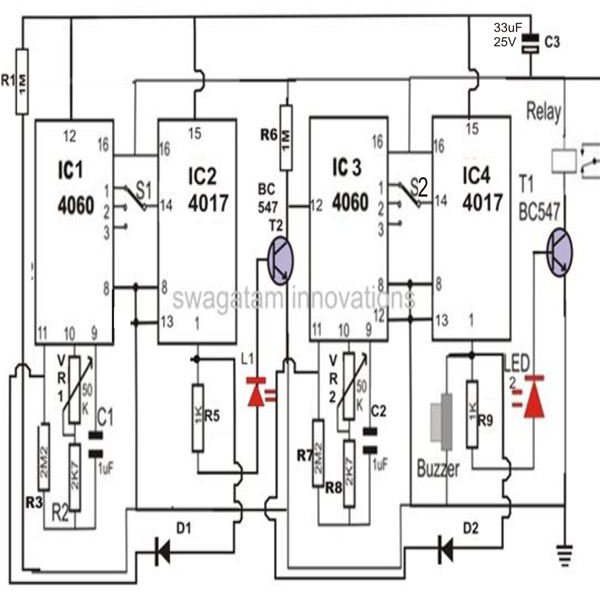
Build a Two-Stage Programmable Timer Counter Circuit
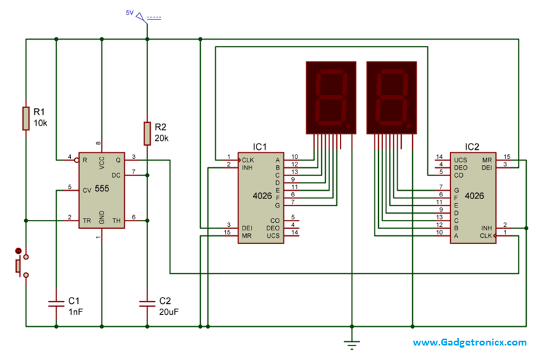
Two Digit Counter Circuit using 7 Segment and IC 4026 ...
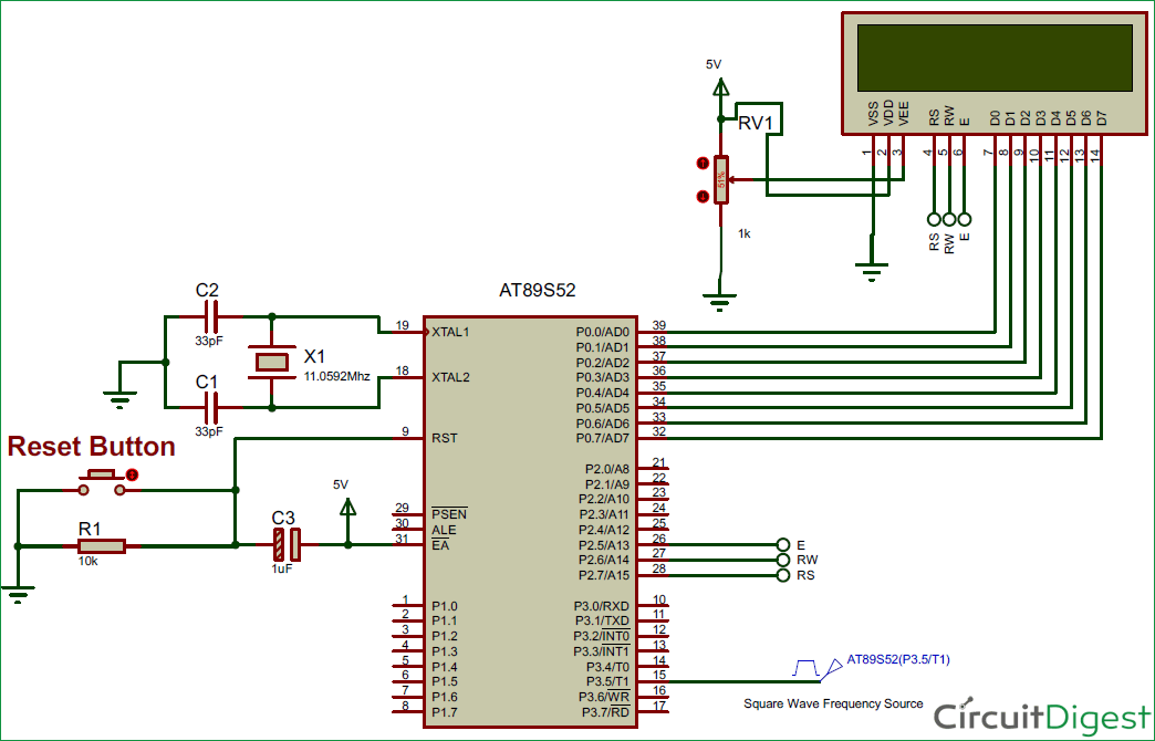
8051 PROGRAMMING: 8051 Microcontroller based Frequency Counter
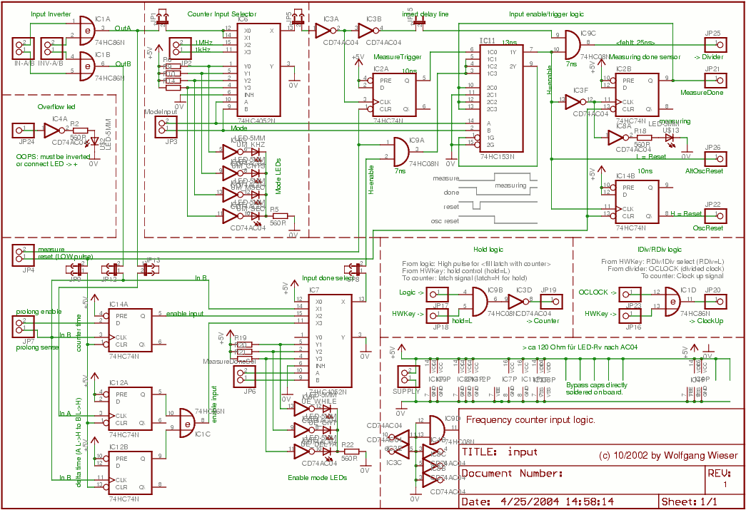
Frequency counter: Input schematic
Counters in Digital Logic - GeeksforGeeks

Simple Tachometer Circuit or Revolution Counter Circuit ...

CD4510B Types CMOS Presettable Up/Down Counters - Tok

74LS192 counter based A simple scoring game circuit ...

59 Counter Circuit Diagram | schematic and wiring diagram
Ripple Counter Circuit Diagram and Timing Diagram. Give your answer in a tabular form showing the present state QA, QB, QC, J-K inputs (JA, KA, JB, KB, JC, KC) and the next state QA+. If a counter resets itself after counting n bits is called "Mod- n.

0 Response to "0 59 Counter Circuit Diagram"
Post a Comment