0 10 Dimming Ballast Wiring Diagram
0 10 Dimming Ballast Wiring Diagram. Don't wire all the ground leads together on the schematic, that is what the. Improper socket application will damage the ballast and void the ballast warranty.

Don't wire all the ground leads together on the schematic, that is what the.
Parallel relationship is more complicated than the series one.
0-10v Dimmer Wiring Diagram

Mark 10 Dimming Ballast Wiring Diagram - Wiring Diagram

0 10 Volt Dimming Wiring Diagram | Free Wiring Diagram

Advance Mark 7 Dimming Ballast Wiring Diagram - Wiring ...
0-10v Dimmer Wiring Diagram

0 10V Dimming Wiring Diagram : Yv 6552 0 10v Dimming Led ...
Dimming Ballast Wiring Diagram

Lutron Dimming Ballast Wiring Diagram - Wiring Diagram And ...

0 10v Dimming Ballast Wiring Diagram | Free Wiring Diagram
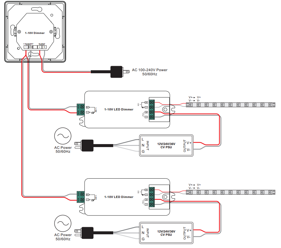
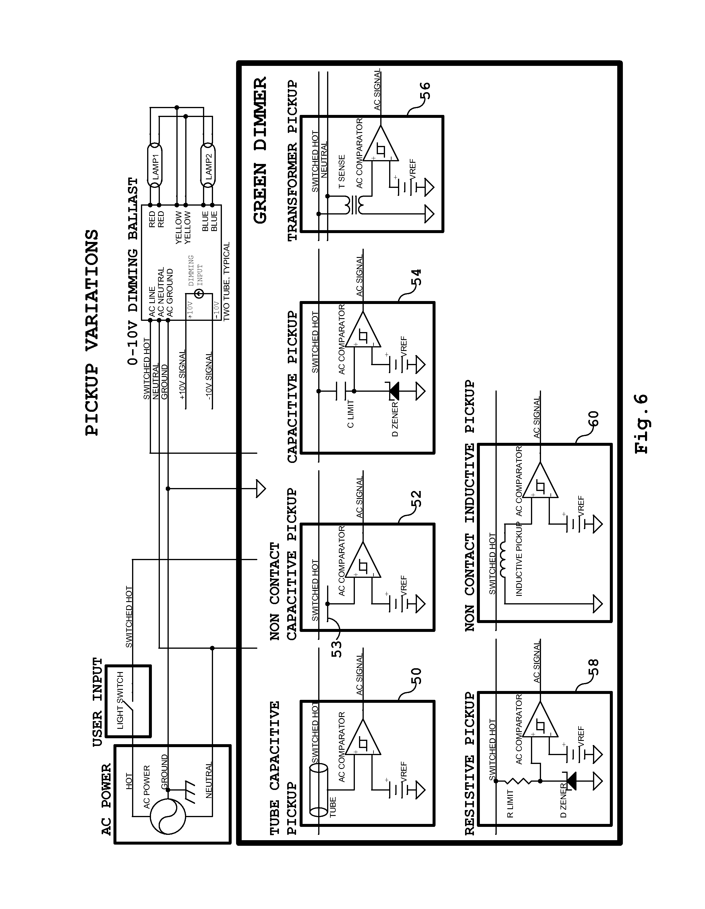
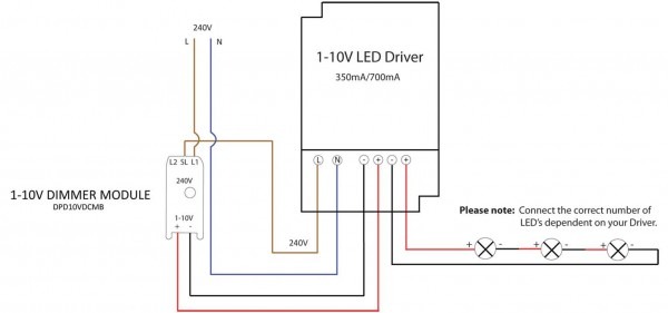
For example , when a module is usually powered up also it sends out a signal of half the voltage in addition to the technician will not know this. Схемы и радиоэлектроника: ЭЛЕКТРОННЫЙ БАЛЛАСТ ДЛЯ ЛАМП ЛДС, Схемы источников питания - читайте на портале Радиосхемы. A Sink Type dimmer is required. The basic wiring scheme consists of a high-voltage circuit wiring and a secondary set of low-voltage control/signal leads which connect the ballast (driver) to the dimmer control.

0 Response to "0 10 Dimming Ballast Wiring Diagram"
Post a Comment