Schematic Wiring Diagram Ground
Schematic Wiring Diagram Ground. For example, how the horns are powered and connected to the controller on your steering wheel. Fellow author throbscottle has created a great Instructable on How to reverse engineer a schematic from a circuit board.

A wiring diagram is a type of schematic that uses abstract pictorial symbols to show all the interconnections of components in a system.
A wiring diagram (also named electrical diagram, elementary diagram, and electronic schematic) is a graphical representation of an electrical circuit.

25 Propose A Plausible Synthesis For The Following ...

wiring diagram ground - Wiring Diagram and Schematic
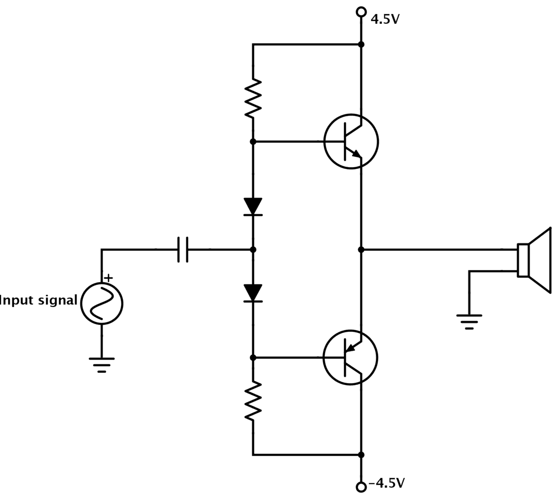
What is Ground in Electronic Circuits

M - Wiring Diagram - Porsche Repair Blog

2n Ford Tractor 12 Neg Ground Wiring Diagram

31 Above Ground Pool Bonding Diagram - Wiring Diagram List

GFI Ground Fault Interrupter Wall Wart
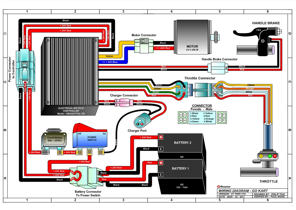
Razor Ground Force Electric Go Kart Parts ...
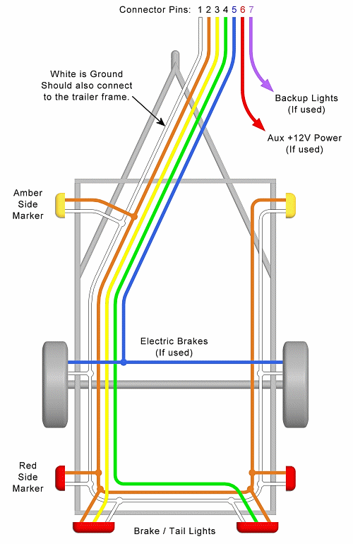
Trailer Wiring Diagram - Lights, Brakes, Routing, Wires ...
WIRING DIAGRAM A wiring diagram shows, as closely as possible, the actual location of all component parts GROUND (If used). For example, how the horns are powered and connected to the controller on your steering wheel. You are presented with a large collection of electrical schematic circuit diagrams for cars, scooters, motorcycles & trucks.

0 Response to "Schematic Wiring Diagram Ground"
Post a Comment