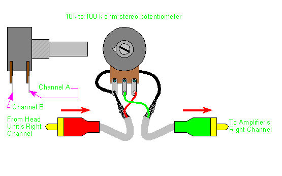
K Ohm Potentiometer Switch Wiring Diagram
K Ohm Potentiometer Switch Wiring Diagram. Ali walks you through the entire straight-forward process here-- but first, visit Galco.com for everything you need. Eventually, I'm going to wire this circuit directly into the guitar's pickup wiring.

Hi Shahzada, could you please confirm the reason for the difference in wiring options between the diagram above and what was used in the video tutorial.
Composition and contents of wiring diagrams.

50k ohm Dual Linear Rotary Potentiometer with D-Shaft ...

1x Tesla TP281b/32B - Rotary Switch Potentiometer 1A 250V ...

The Guitar Wiring Blog - diagrams and tips: Volume Drop ...

Potentiometer - Alpha, Audio, SPST Switch | Antique ...
Headset volume issue | Velocity Reviews
Linear Taper Potentiometer with Switch | 10K Ohm | 31VM401

Rotary switch LA42DWQ 22 22mm 1K 2K 5K 10K Ohm Variable ...

1k ohm Logarithmic Rotary Potentiometer with Switch ...

10k Ohm Potentiometer Switch Wiring Diagram
This article is about digital potentiometers. In the above circuit diagram, you can see there is only one resistor in the potentiometer but the slider divided the resistor into two. A potentiometer is a simple knob that provides a variable resistance, which we can read into the Arduino board as an analog value.

0 Response to "K Ohm Potentiometer Switch Wiring Diagram"
Post a Comment