Pin Timer Relay Wiring Diagram
Pin Timer Relay Wiring Diagram. star delta timer connection In this video I practically explained the time relay function and time relay. A relay is typically used to control a component that draws high amperage.

star delta timer connection In this video I practically explained the time relay.
Wiring a Denso relay is extremely simple.
Macromatic : Time Delay Relays Time Ranger Programmable ...

Dayton Time Delay Relay Wiring Diagram Gallery

Dayton Time Delay Relay Wiring Diagram Gallery
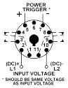
8 Pin Timer Relay Diagram
8 Pin Timer Relay Wiring Diagram - Wiring Diagram and ...
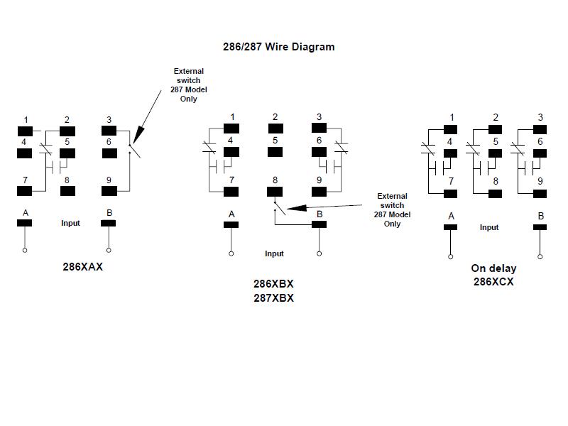
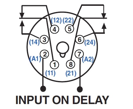
Item # 286XCXC-010-120VAC, 286/287 Series - Squre Base ...

[AB_0222] Wiring A Timer Relay Download Diagram

Wiring Manual PDF: 120v Relay Wiring Diagram

Pin on Inr Wiring Diagram
The low-voltage side has a set of four pins and a set of three pins. We just need: Connect an Arduino's pin to the IN pin of the relay. star delta timer connection In this video I practically explained the time relay.

0 Response to "Pin Timer Relay Wiring Diagram"
Post a Comment