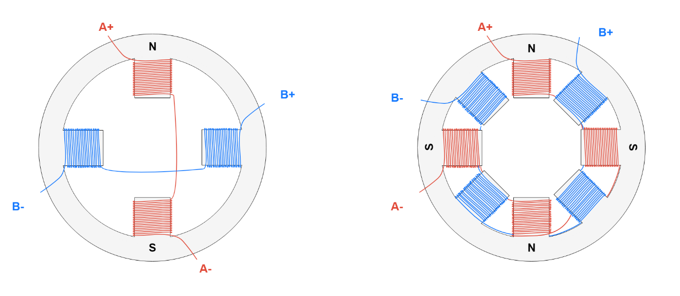
Tooth Stator Wiring Diagram
Tooth Stator Wiring Diagram. Obviously, the more rotor teeth and or stator coils would result in more control and a finer step angle. Originally used for securing Kohler alternator/stator wires to bearing plate.

PARAMETER Use built in MAP Built in MAP offset MAP Range MAP Offset Analog input Built in BARO offset Enable digital filter.
All diagrams are presented in JPEG (.jpg) format.

Lambretta Stator Plate Wiring Diagram - Wiring Diagram
Brushless Motor Muti-Pole Stator Needle Winding Segmented ...
Stepper Motors: Types, Uses and Working Principle ...
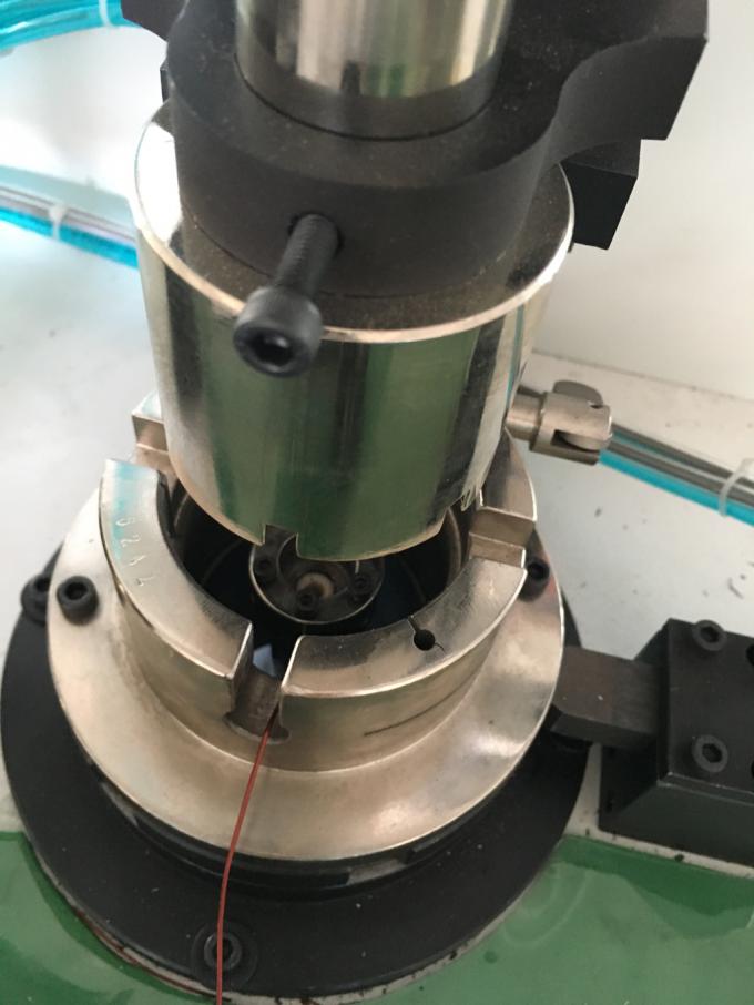
Muti Poles Brushleses Electric Motor Stator Teeth Smart ...

(PDF) Simulink Controller for a Reluctance Motor With Four ...

200cc Yamaha Blaster Wiring Diagram - Wiring Diagram

Stator Plate Wiring Diagram - Wiring Diagram

The port wiring diagram of the prototype when it is ...

LRK and DLRK Winding Question - RC Groups
Rotate the motor's shaft and feel for rubbing. Refer to the wiring diagram to verify the motor is wired correctly. Construction and working principle of a three-phase induction motor.

0 Response to "Tooth Stator Wiring Diagram"
Post a Comment