Pin Relay Base Wiring Diagram
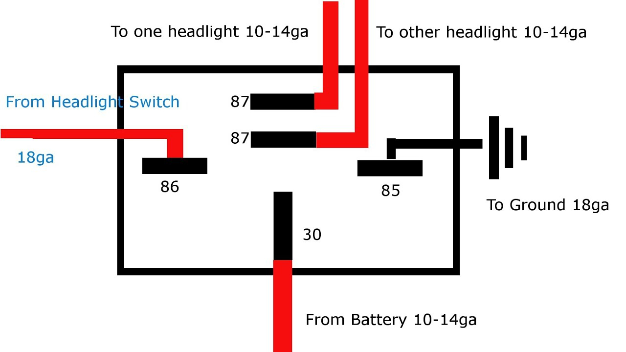
Pin Relay Base Wiring Diagram. If a large enough positive current is now driven into the Base to saturate the NPN transistor, the current flowing from Base to Emitter (B to E) controls the larger. The wiring diagrams below serve to show each pin of the relay and what they each represent, so a user can know how to wire them up when connecting them.
Use Relay Location and Electrical Wiring Routing sections to find each part, junction block and wiring harness Numbers outside connector codes indicate the pin numbers of both male and female connectors.
Provides circuit diagrams showing the circuit connections.
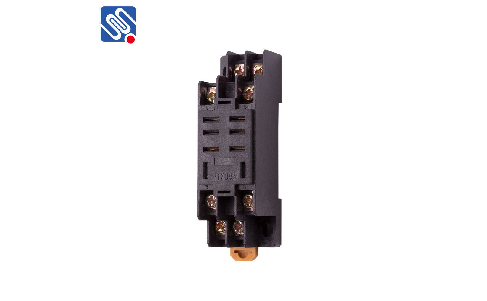
8 pin relay base diagram(PTF08A )_meishuoen

Amazon.com: Uxcell 4PDT Electromagnetic Power Relay with ...
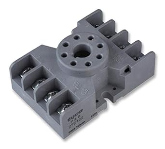
Potter and Brumfield 27E122 Blade and Octal Relay Socket ...

14 Pin Relay Wiring Diagram - Finder Relay Wiring ...

automotive relays 12V 30/40 amp 5 pin SPDT designed ...

DPDT 110VAC 10A 8 Pin Octal Power Relay Technical Data

Solid State Timer Wiring Diagram - Hanenhuusholli

Socket Relay Wiring Diagrams For 8 Pin | schematic and ...

How to wire Pin timers
The wiring diagrams below serve to show each pin of the relay and what they each represent, so a user can know how to wire them up when connecting them. Wiring a Denso relay is extremely simple. Typical output signal circuit is shown in the following diagram: Servo drive.

0 Response to "Pin Relay Base Wiring Diagram"
Post a Comment