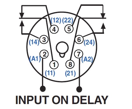
Pin Timer Wiring Diagram
Pin Timer Wiring Diagram. The below diagram is on delay timer wiring diagram. Bunn SRUA Manual Online: timer, Wiring Diagram.

Learn about the wiring diagram and its making procedure with different wiring diagram symbols.
The below diagram is on delay timer wiring diagram.

Anly Timer Wiring Diagram
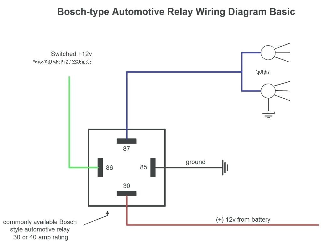
Bosch 4 Pin Relay Wiring Diagram | Wiring Diagram

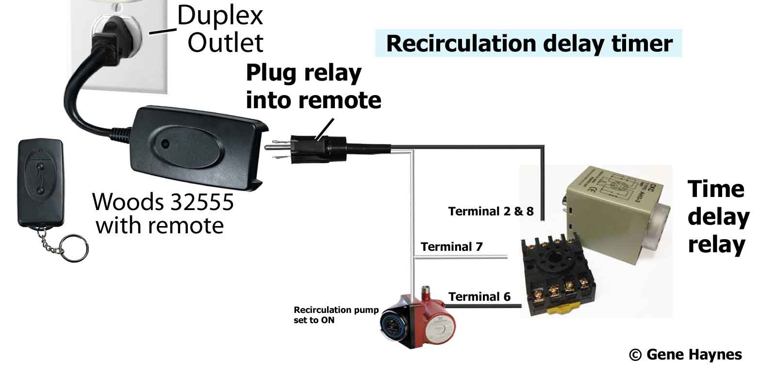
How to wire Pin timers

star delta starter control circuit diagram with timer ...

SOLVED: Need wiring diagram SPST power to timer timer to ...

How to wire Pin timers
Wiring Diagram For Ckhkc Delay Timer 8 Pin
8 Pin Timer Relay Diagram
11 Pin Timer Relay Wiring Diagram
F ELECTRICAL WIRING DIAGRAM (System Circuits). It shows how the electrical wires are interconnected and can also show where fixtures and components may be connected to the system. General Purpose Electronic Timers and Counters. • Pin-style terminals • Standard ON/OFF flag indicator • Electrical schematic on face • Clear cover for visual inspection Wiring Diagrams U.

0 Response to "Pin Timer Wiring Diagram"
Post a Comment