0 10 V Dimming Ballast Wiring Diagram
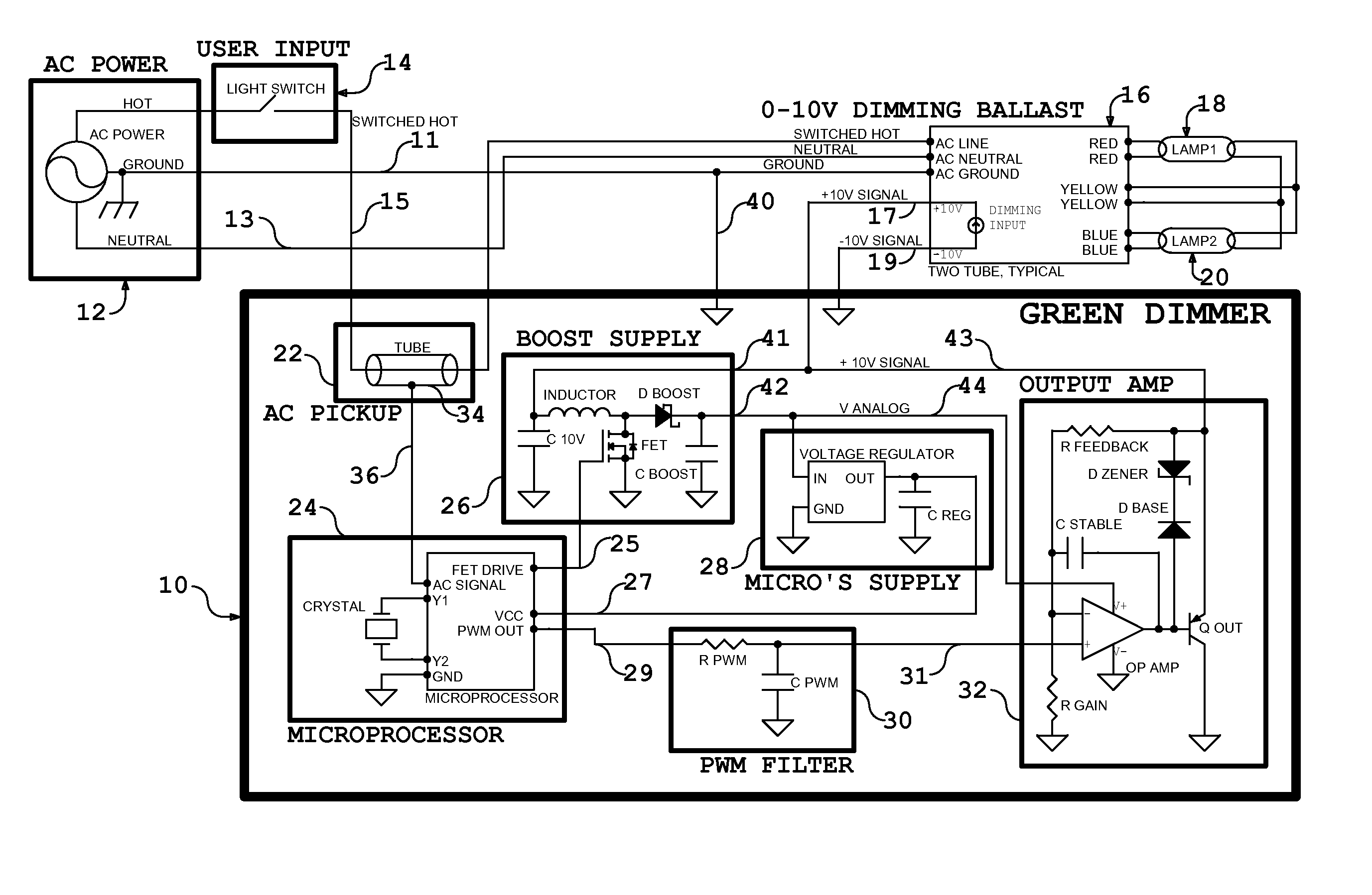
0 10 V Dimming Ballast Wiring Diagram. The ballast control section also pro-vides the necessary circuitry to perform closed-loop dimming, lamp fault detection, shutdown and auto-restart. Dimming Ballasts Universal Lighting Technologies SuperDim® Ballasts.

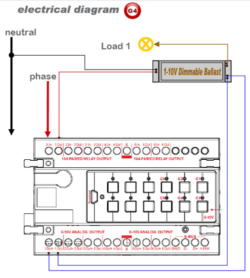
Ballasts controlled by this method require only two control wires.
Dimming With ON / OFF Control For Drivers Which Support Dim To OFF Capability Power Wiring Not Shown—See Lighting Device For Wiring.

Lutron Dimming Ballast Wiring Diagram - Wiring Diagram Schemas
Dimmable Ballast Wiring Diagram

0 10v Dimming Ballast Wiring Diagram
Lutron 0 10v Dimmer Wiring Diagram

Dimming Ballast Wiring Diagram - Wiring Diagram and Schematic

0 10v Dimming Wiring Diagram

0 10 Dimming Ballast Wiring Diagram - inselstaat im pazifik

Mark 10 Dimming Ballast Wiring Diagram
0 10v Dimming Ballast Wiring Diagram
A wiring diagram is a schematic which uses abstract pictorial symbols to exhibit all of the interconnections of components in a system. Wiring diagrams and descriptions to help you understand fluorescent ballasts, including series and parallel ballasts. Simply put, the control signal is a DC voltage that varies between zero and ten volts.

0 Response to "0 10 V Dimming Ballast Wiring Diagram"
Post a Comment